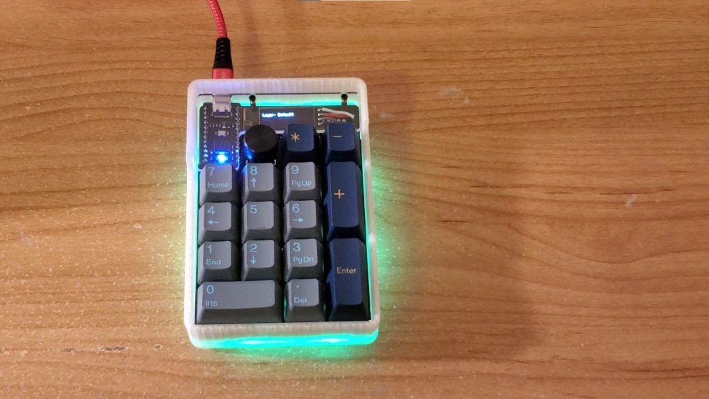
Overview:
The Tidbit Numpad is a mechanical numberpad kit sold by nullbits. This keyboard supports multiple layouts with different keys, rotary encoders, and OLED displays.
For my Tidbit Numpad build, I have assembled and soldered the numberpad, coded and flashed custom firmware onto the board, as well as cadded and 3D-printed a case for the keyboard.
Process:
Electronics
By following the public tutorial on Github, I assembled and soldered different components onto the PCB. This included SMD LEDs, a reset button, 1N4148 diodes, a TRRS Jack, the BIT-C microcontroller, a rotary encoder, the 0.91” OLED display module, and mechanical keyboard switches.


Software
With the numpad assembled, I coded custom keyboard functions in C, converted the files to .hex files through MSYS2, and used QMK Toolbox to flash it onto the board. I found the QMK public tutorial to be very helpful in setting up MSYS2 and QMK Toolbox.
My custom firmware has two modes or layers: Default and RGB. The OLED display shows the current layer and rapidly tapping the rotary encoder twice switches between the two layers.


The default layer performs normal number pad functions, with the BIT-C LED signifying whether or not Num-Lock is on and the rotary encoder itself representing Backslash. Turning the rotary encoder changes volume.
The RGB layer has multiple RGB modes and setting selections. In addition, turning the rotary encoder scrolls up or down and the Subtract key toggles Num-Lock. The Add key also launches the Calculator app and automatically moves to the Default Layer so the user can immediately start typing in calculations.
These functions are defined in keymap.c of my custom firmware.
Hardware
After flashing firmware and completing the numpad build, I decided to replace the back plate with my own case. Using a digital caliper, I was able to take accurate measurements of the numpad and design the case in Fusion 360. This case was then printed in PLA on a Creality Ender 5.


Final Product: